This renewable energy project was majority funded by the Illinois Clean Energy Community Foundation (ICECF), U.S. Department of Energy (DOE), and Commonwealth Edison Company (ComEd) as part of the larger IIT Microgrid project for enhancing the campus security, economics, reliability, resilience, and sustainability.
Azimuth Energy (St Louis, MO, USA) provided the development support, permitting, engineering, and construction to implement this project, as well as the other nanogrids on the IIT campus. The IIT Microgrid project started in 2008 and has continued to be expanded over the years.
SUMMARY STATEMENT
From November 2017 to March 2019, the Illinois Institute of Technology (IIT), in collaboration with Azimuth Energy, designed, developed, and implemented a renewable-based battery project that converted the IIT’s Crown Hall, a National Historic Landmark, into a nanogrid operation. This project engineered, furnished, and installed a new Tesla Energy battery energy storage system (BESS) which provides 300 kW of power and 500 kWh of energy storage to the Crown Hall building. The BESS can provide temporal load shifting, peak load shaving, black start capacity, demand response (time-of-use curtailment), and intentional islanding from the grid.
The Crown Hall Nanogrid, which is located in Loop 5 of the IIT Microgrid, also includes a 80 kW solar photovoltaic (PV) System and complex islanding control system, which allows Crown Hall to be islanded from the IIT Microgrid in critical conditions and be operated as a stand-alone electrical system. In island mode, the Crown Hall Nanogrid allows the building to be operated for approximately one half of a typical day based on its energy consumption pattern.
The entire campus of IIT is operated as an islandable microgrid. The difference between a microgrid and a nanogrid is that a nanogrid is a scaled-down version of a microgrid, which includes a critical building within a microgrid, offers its own operational specifications, and will be operated as a separate entity in critical circumstances. Examples of nanogrid include the surgery building within a hospital campus or a data center within a sensitive government operation which must remain operational under any conditions. In addition to the Crown Hall Nanogrid, IIT Microgrid is operating its Stuart Building (Data Centre) and Keating Hall (Sporting Center) as two nanogrids; both projects also engineered and constructed by Azimuth Energy.
PROJECT NEED AND OVERVIEW
The S. R. Crown Hall (See Figure 1) is home to the College of Architecture at IIT, a modern masterpiece that Time magazine called “one of the world’s most influential, inspiring and astonishing structures.” Designed by Ludwig Mies van der Rohe in 1956, Crown Hall cohesively represents his architectural concepts and theories in their most complete and mature form. Crown Hall is a straightforward expression of construction and materiality, which allows the structure to transcend into art. Its refinement and innovation place Crown Hall among the most distinguished buildings of its age and define its importance in the history of architecture.
The column-free open plan of the main floor of Crown Hall demonstrates Mies’ innovative concept of creating universal space that can be infinitely adapted to changing use. Its expansive size of 120′ x 220′ feet in floor area, with a ceiling height of 18 feet, allows individual classes to be held simultaneously without disruption while maintaining creative interaction between faculty and students. The roof of the building is suspended from the underside of four steel plate girders. The girders are themselves supported by eight exterior steel columns, spaced at 60-foot intervals. The interior is divided by free-standing oak partitions that demark spaces for classes, lectures and exhibits. Crown Hall was granted National Historic Landmark status in 2001 by the National Parks Service, U. S. Department of the Interior.
After nearly 50 years in use, Crown Hall was restored in 2005 by Architects Mark Sexton and Gunny Harboe who led the $3.6 million restoration project. The Crown Hall continues to inspire the cutting edge of architecture and design for decades to come. The Crown Hall’s restoration project received the 2006 Richard H. Driehaus Foundation Preservation Award for Project of the Year from Landmark Illinois, a 2006 Citation of Merit from AIA Chicago, and a 2005 Honor Award from Chicago Landmarks Commission.
Just as the Crown Hall restoration marvelously preserved the architectural beauty of this National Historic Landmark, we believe the introduction of the latest renewable energy and energy storage technologies to this building also elevates its stature as an energy efficient landmark in the City of Chicago. With the generous support from ICECF and ComEd, this project acquired and installed solar PV and battery storage units in Crown Hall to make it an energy efficient, green, and reliable building. The solar PV and battery installations at Crown Hall will also be used to analyze and demonstrate the economics, reliability, resilience, sustainability, and security benefits of supplying clean energy to a national landmark.
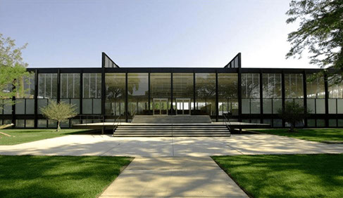
Figure 1: IIT’s S.R Crown Hall (a national historic landmark)
PROJECT SITE
The IIT’s Crown Hall is located at 3360 South State St., Chicago, IL (Figure 2). This location was selected due to the architectural significance of the building and the desire to not interfere with the visibility of the building. Figure 3 depicts the location of the Crown Hall at the IIT Microgrid. IIT Microgrid encompasses 35 buildings which are divided into seven high-reliability electrical loops demonstrated in Figure 3. The Crown Hall (circled in red) is located in Loop 5. The PV panels and BESS located in the Crown Hal Nanogrid are optimally scheduled by a control unit for optimizing the electricity supply to the building. The additional generating units located within the IIT Microgrid will supplement the electricity generated at the Crown Hall.
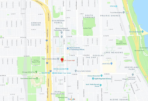
Figure2: Location of the Crown Hall Nanogrid (3360 South State St., Chicago, IL)
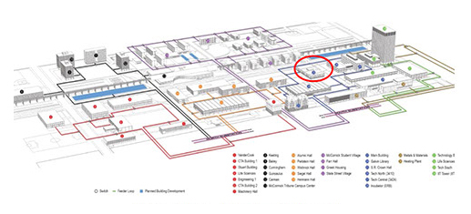
Figure 3: ITT’s Microgram with the Crown Hall Nanogrid
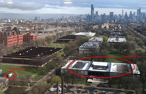
Figure 4: Crown Hall Nanogrid: 80 kW Solar, 300 kW / 500 kWh Tesla BESS
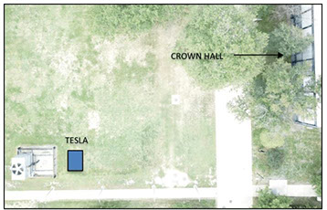
Figure 5: Tesla Battery Plant Location
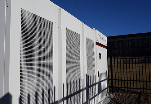
Figure 6: 500 kWh Tesla Energy battery plant
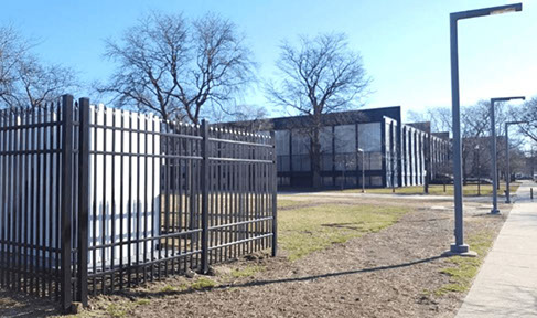
Figure 7: Tesla Energy battery plant located adjacent to the IIT’s Crown Hall (background)
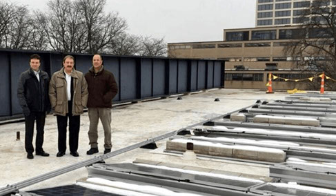
Figure 8: 80 kW of PV installed on the roof of Crown Hall
SOLAR PV INSTALLATION
The design layout maximizes the PV capacity considering the shading of nearby trees. The layout will experience roughly 3% shading or irradiance due to the trees surrounding the building. As Crown Hall is a national landmark with a unique architecture design, certain limitations were taken into consideration for the design including (1) National Historic Landmark review of the proposed plan, (2) approval by the Areawide Development Review Committee (ADRC), (3) consideration of no line of sight exposure from ground level of the landmark building, (4) roof installations must be reviewed by the designated roofer for the landmark building, and (5) electrical connections must not disturb the existing infrastructure within the landmark building. The designed arrangements as shown in Figure 9 have been done to secure the ADRC requirements. In addition, the “line of sight” requirements were met in the Figure 9 design and were followed by the general contractor of the project. Having the solar PV system in the three bays, as shown in Figure 9, holds back some distance from the north and south roof edge which satisfy the line of sight requirement as the girders will help block the view. An illustrative line of sight study is shown in Figure 9, which is an elevation rendering a sight line from an observer standing on the ground. The 15’ setback is designed to have a long sightline.

Figure 9: Line of Sight Elevation for the Rooftop PV System
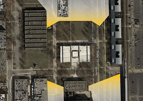
Figure 10: Line of Sight Plan View for the Rooftop PV System
CONSTRUCTION BACKGROUND
The interconnection and configuration of islanding capabilities also required extensive work in the electrical basement. This included stepping down the Tesla BESS voltage to match the Crown Hall building voltage, and interruption of the building service to install the islanding relays. Figure 11 is an diagrammatic excerpt from the construction drawing package depicting the work in the basement, outside, and the roof.
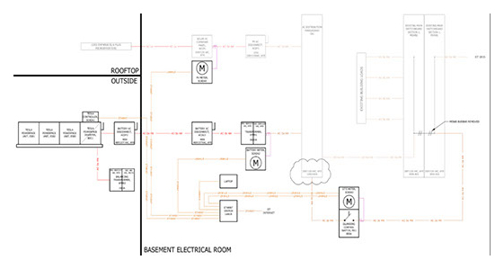
Figure 11: Excerpt of Azimuth Energy’s Construction Drawing
The floor plan as shown in Figure 12 depicts the layout of the electrical room after this project. The only existing components prior to the Tesla and PV projects were the MSWB1 and MSWB2 switchboards shown in the lower-right corner. Installing this equipment required the removal of abandoned concrete pads for previously removed equipment, and the relocation of many installed control systems mounted on the walls in this part of the electrical basement. Figure 13 shows some of the electrical equipment installed in the basement of Crown Hall required to connect the PV and the BESS devices to the building’s existing electrical system – to comply with the building code, best practices, international standards, and allow the full functioning of the nanogrid system and controls.
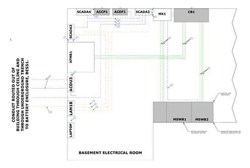
Figure 12: Plan Layout of the Basement Electrical Room
SUMMARY OF OPERATION STRATEGY
The 500 kWh Tesla BESS provides these primary functions: (1) backup for the building; (2) continuous peak shaving; (3) time-block demand reduction; and (4) allow the islanding of the building. The control system also will allow the building to be intentionally islanded from the IIT electrical distribution.
The Tesla BESS design is based on a typical daily load curve for Crown Hall, as depicted in Figure 14. This graph also includes a potential 10% future growth factor. This load curve was recorded from the IIT Microgrid monitoring system in May 2019. This growth factor will ensure the Tesla BESS can support the entire building load in case the load increases. Plus, it adds stability in case of high load combined with low renewable generation.
The Crown Hall demand does not decrease at night, as is often the case with commercial buildings. This condition leads to the conclusion that any energy efficiency measures will potentially be effective in reducing overall energy consumption in Crown Hall, which would increase the effective operation of the Tesla BESS and the PV System.
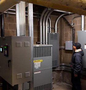
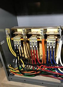
Figure 13: Electrical Equipment Installed in the Basement
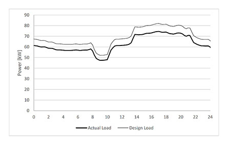
Figure 14: Daily Load Profile for Crown Hall, Current/Actual and 10% Growth
Figure 15 shows the typical daily PV energy production from the Crown Hall rooftop PV System on a sunny day, and the resulting power and energy used from the grid. The PV production reduces the building demand and often backfeeds the power to the campus microgrid.
Figure 16 demonstrates the real-time building data when the PV energy production has reduced the grid power.
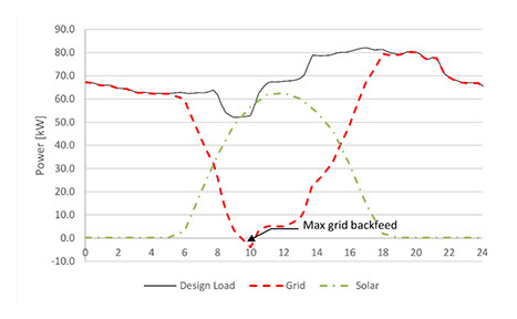
Figure 15: Daily Demand Curve With PV Production
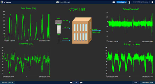
Figure 16: Crown Nanogrid Data Monitoring
PEAK SHAVING
The Tesla BESS is designed to reduce and control the peak demand and keep the maximum grid power within one standard deviation of the average design load during all hours of the day. This can occur when high-current equipment turns on, often being air conditioning compressors, pumps, or other mechanical equipment.
That threshold is set to of 100 kW, as shown in Figure 17. When the building power demand begins to exceed 100 kW, the Tesla controller will automatically adjust its output voltage so that the battery supplies the power demand above 100 kW (up to a maximum of 350 kW). In this example, the BESS discharges initially to meet the peak load, and then charges from the grid later when demand drops below 100 kW.
When operated in Peak Shaving mode, the Tesla BESS recharge is limited to 25 kW. This is to avoid increasing demand charges during recharge and also to reduce the stress on the grid.
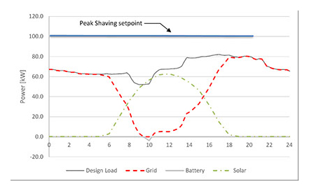
Figure 17: Peaking Shaving Setpoint at 100 kW
DEMAND RESPONSE
The Tesla Energy plant controller is also configured to limit power consumption and reduce demand charges from the utility that are based on time-of-use tariffs and grid demand. This is different from the peak-shaving function in that the Demand Response operates only during specific intervals of the day when utility tariffs are increased due to grid demand.
During the daily time intervals with higher demand rates in the tariff structure, the Tesla System will be discharged to maintain grid power below a preset limit. The ComEd demand peak hours are 12:00 pm to 10:00 pm, although the system can also respond to real-time signaling from the utility grid where the time window may change during the day.
The scenario depicted in Figure 18 shows this performance with no PV offset (a cloudy day).
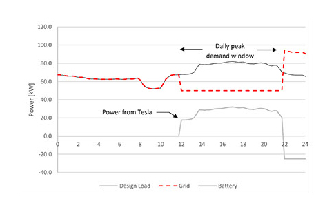
Figure 18: Daily Demand Response Window, 50 kW Max Demand Setpoint
SYSTEM INTEGRITY
The Tesla System will charge and discharge on a daily basis. To optimize utility and cost savings, the controller is programmed to maximize power reduction while still fully recharging prior to the demand window the next day. This is done by setting the minimum demand-response power setting to still enable full recharge during the “off hours”. Figure 19 shows a 48-hour period, demonstrating that the Tesla BESS fully recharges each day before entering the 12:00-to-22:00 response time period.
Note that this scenario is not including the benefit of the PV System (assuming worst-case cloudy conditions).
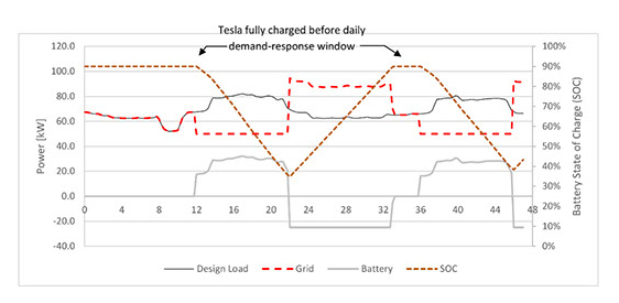
Figure 19: Battery State of Charge, 48 Hours
The scenario in Figure 20 depicts the same demand-reduction scheme as the scenario shown in Figure 19 but includes the PV System energy production. This system is designed for the worst-case scenario of high load with no PV energy production (Figure 15) to ensure the batteries are never fully depleted. In the expected-case scenario in Figure 20, the PV allow the batteries to remain fully charged for most of the day under the design load (10% higher than actual load). Under the actual load, with the PV System operational (the sun shining), the batteries might not be used at all to achieve the targeted demand-reduction performance.
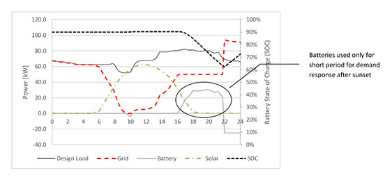
Figure 20: Battery State of Charge, with PV
ISLANDING OPERATION
When the Building is islanded, the load is carried by the Tesla BESS in parallel with the rooftop PV System. Should the battery become depleted (less than 10% State of Charge, “SoC”) because the sun isn’t shining, the Tesla BESS reverts to Standby until the grid is restored.
Supervisory Control and Data Acquisition (SCADA)
The control technology embedded in the Crown Hall Nanogrid is a collaborative system with the IIT Microgrids (Figure 21). The SCADA (Supervisory Control and Data Acquisition) system for the IIT Microgrid (Figure 21) is updated every 5 seconds which will allow the IIT campus to control the entire microgrid system in real time including the Crown Hall Nanogrid. The SCADA system gathers the real-time data on building energy consumptions as well as the status of PV and battery storage units. The IIT Microgrid operators utilize the real-time data to optimize the delivery of electricity to the Crown Hall Nanogrid. Figures 22 and 23 display the historical data collected over the last month and past 15 minutes, respectively. In particular, Figure 23 shows that the battery keeps the grid demand below 50kW during peak hours (12PM-10PM).
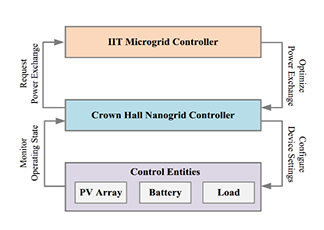
Figure 21: SCADA Configuration
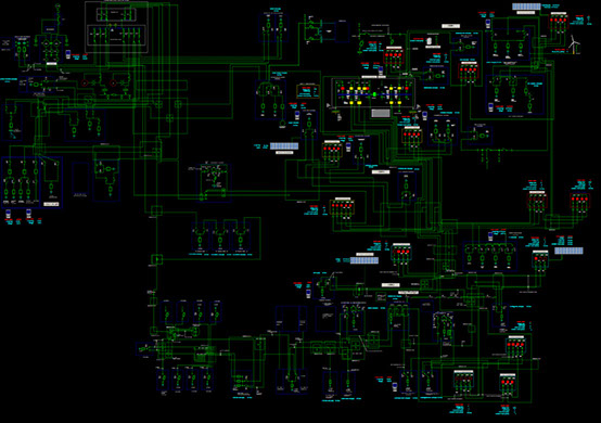
Figure 22: One-line Diagram of IIT Microgrid SCADA System (based on PI OSIsoft Coresight)
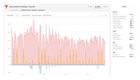
Figure 23: Crown Hall Nanogrid Data Monitoring (last 30 days)
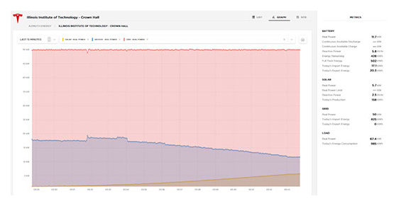
Figure 24: Crown Hall Nanogrid Data Monitoring (last 15 minutes)
The IIT Microgrid applies the same SCADA system for the monitoring and control of other renewable energy sites and nanogrids at IIT. The actual locations of these sites are depicted in Figures 25 and 26. The collected SCADA data is used for the real-time simulation of the campus operation which is discussed next.
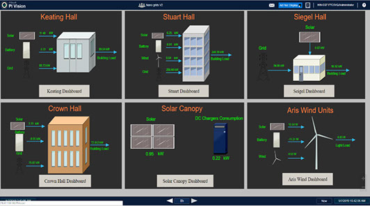
Figure 25: IIT Renewable Energy Installations and Nanogrids
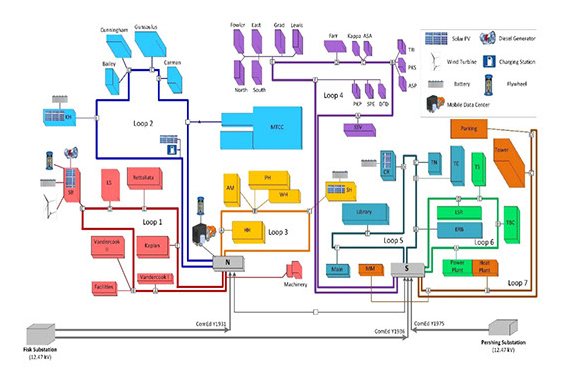
Figure 26: Azimuth Energy IIT Campus Renewable Energy and Nanogrid Installations
Real-Time Simulation of Power Flow in the Crown Hall Nanogrid
We use Real-time Digital Simulator (RTDS) for the detailed modeling of the power and control system components present in the IIT Microgrid. RTDS operates in real time, allowing the user at IIT to interface physical equipment with the simulated model in order to test and validate the operation of microgrid protection and control devices under realistic conditions.
Figure 27 shows the RTDS site for the monitoring and the control of the renewable energy sites and nanogrids at IIT. The RTDS equipment is located on the left side the control room. RTDS allows IIT to simulate in real time the actual behavior of the microgrid operation should a critical situation occurs anywhere at the IIT Microgrid site. Figure 28 shows a sample result of power flows across IIT cable lines.
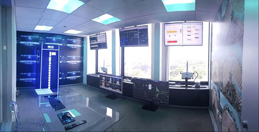
Figure 27: IIT Real-time Digital Simulator (RTDS)
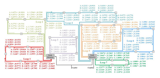
Figure 28: Three-Phase Power Flow of the Loop-based IIT Microgrid
EDUCATIONAL OUTREACH
This project is now part of the educational and publicity efforts of the Robert W. Galvin Center for Electricity Innovation at IIT. The Robert W. Galvin Center at IIT has become a focus of smart grid/renewables education and training in the nation and around the world, hosting two to three groups of visitors every week from K-12 students to senior citizens, from smart grid/renewables vendors to domestic and international experts of smart grid/renewables, from electrical engineers to venture capitalists, from general public to politicians. Every year, tens of engineering and science students at IIT participate in the design of the operation of the IIT Microgrid and its various nanogrids.
The two fliers (depicted in Figures 29 and 30) are among handouts which explain the nature of the work at the Galvin Center. In addition Galvin Center is equipped with a tabletop model of the IIT Microgrid (Figure 31) which helps the staff explain the nature and the functions of distributed energy systems in practical terms.
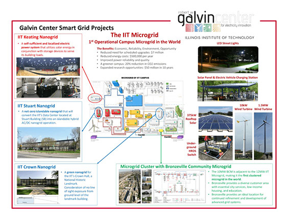
Figure 29: IIT Microgrid Brochure
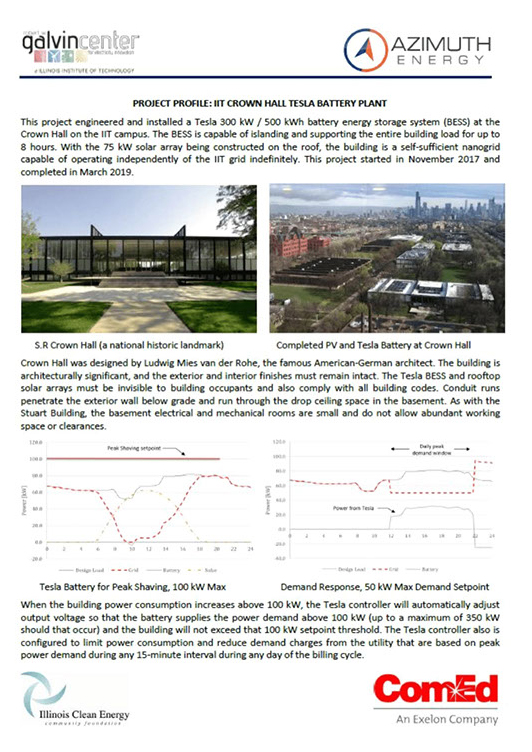
Figure 30: Crown Hall Nanogrid Brochure
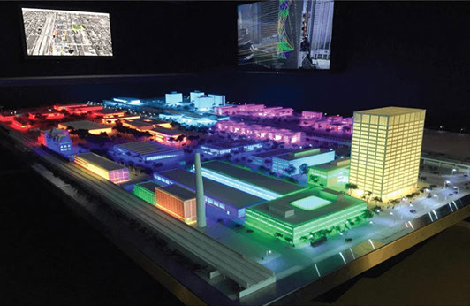
Figure 31: Tabletop Model of the IIT Microgrid
– – –
This article adapted from the 2019 Submittal by IIT to the Illinois Clean Energy Community Fund (ICECF)
